
Laser Cutting Fume Extraction
Laser cutting fume extraction is mostly a particle-size problem. A laser does not make smoke the way a flame does — it vaporises the material and the vapour condenses into particles small enough to behave like a gas, which is why a 0.3 µm cartridge and a correctly placed hood matter more here than airflow alone.
15.4–86 nm
particles measured from CO₂ laser cutting of acrylic
73–89%
of the particles emitted were below 300 nm
5 stages
graded filtration, ending in an odour stage — a single cartridge does not cover laser fume
A cut you cannot see, and a plume you can
The cut is quiet, precise and fast, and the plume it leaves is one of the least visible and least forgiving in a sheet metal shop.
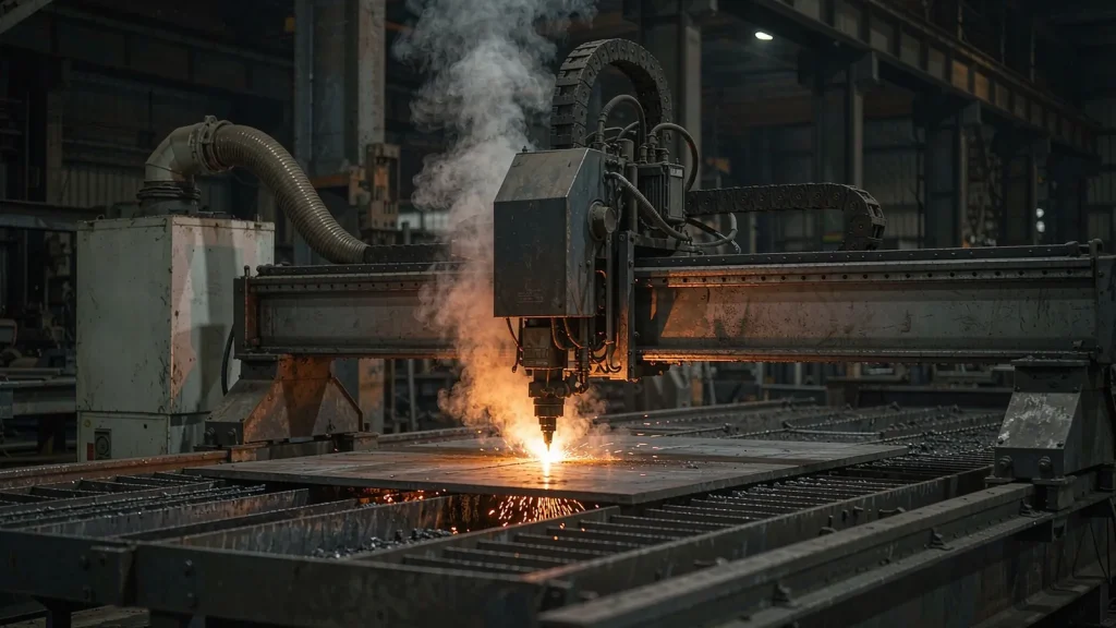
Laser cutting works by heating the material past its vaporisation point. The metal or plastic leaves the kerf as vapour, cools within a few millimetres of the cut and condenses into particles in the nanometre range. Those particles stay airborne for a long time, travel on the slightest draught, and settle on every surface in the shop — including the machine’s own optics, mirrors and lens, which is why the extraction is as much about machine reliability as about the operator.
What is being cut changes what is in the plume. Mild steel produces metal oxide fume. Stainless and galvanised sheet add chromium, nickel and zinc. Coated and painted sheet releases the coating as well as the substrate. Plastics, acrylic, rubber, leather and composite materials produce organic condensates that smell long before they are dangerous by any measure you can see on a filter gauge — which is why cutting mixed materials on one machine needs an odour stage, not just a particle filter.
What the particle measurements show
15.4–86 nm
Particle sizes measured from CO₂ laser cutting of acrylic — well below the size any conventional filter class is designed around, and small enough to stay airborne across a workshop.[1]
73–89%
Share of emitted particles below 300 nm in a study of laser processing fume — which is the practical reason the filtration specification across this range is 0.3 µm and not a general dust media.[2]
Metal + organics
Cutting stainless, galvanised or coated sheet puts chromium, nickel and zinc oxide into the plume; cutting plastics and rubbers puts organic condensates into it. The two need different filter stages, so the material list matters as much as the machine.[3]
0.3 µm
The filtration class used across the FAON range — validated for the fine fraction, and paired with a pre-filter stage so the cartridge is not spending its life catching spatter and coarse debris instead of fume.[4]
Full sources are listed under References at the end of this page.
Follow the head, and keep the optics clean
Two things settle a laser installation: where the extraction point sits relative to the cutting head, and how many filtration stages the material mix demands. Airflow is the easy part once those two are right.
Take it at the head, not at the roof
The plume leaves the kerf moving, driven by the assist gas, and it spreads as it slows. A hood at the cutting head — or a slot arrangement at the head on a flatbed — captures before that spread happens; a hood over the bed picks up what has already dispersed. FDQW-8G and FDQW-26G are the compact units for marking stations, engravers and single-head machines, at 0–1,300 m³/h and 0–1,400 m³/h, with five-stage filtration ending in an odour stage and a ten-speed PLC that lets the airflow be matched to the material rather than left at one setting.
Size the bed, then protect the optics
Large-format cutting tables move a lot of air and a lot of fume. FDYC-60Z at 5,000–7,000 m³/h and FDYC-80Z at 10,500 m³/h cover single-table installations, and FDYC-H4-50H (4,500–6,000 m³/h) and FDYC-H8-80H (8,000–10,500 m³/h) are the cabinet units with 92 m² and 184 m² of media for shops running long shifts. Where two heads cut the same bed, the hood arrangement has to be designed for the pair — one hood chasing two heads captures neither reliably.
Units for laser beds and marking stations
Six units cover a marking station, a single-head laser and a large-format cutting table. All of them filter to 0.3 µm and return clean air to the workshop.
What a laser extraction installation includes
- Extraction hood or slot arrangement at the cutting head, or a bed-level arrangement where the head carriage cannot take the weight
- Five-stage graded filtration with a final odour stage for mixed-material machines, plus spare stage-one and stage-two media
- A PLC-controlled unit with a filter-clog alarm, so a loaded cartridge shows up as a reading rather than as haze on the shop floor
- Commissioning with airflow set per material group, and a short operating note listing which setting goes with which family of materials
Tell us what gets cut — steel, stainless, galvanised, aluminium, acrylic, MDF, rubber, leather, composite — and we will confirm which filtration stages the mix needs. This is the single biggest variable in laser extraction.
Laser processes this covers
Sheet metal laser cutting, laser marking and engraving, tube and profile laser cutting, and laser processing of plastics, acrylic, rubber, leather, textiles and composites. Also covers laser welding and laser cladding where the plume is fine-particulate and continuous. Where the process is plasma rather than laser, the fume is coarser and hotter — the plasma cutting page is the better starting point, because the spark and heat load is a different problem.
At the machine
Questions from laser operators
Send us the laser type, material and bed size
Send us the laser type (CO₂ or fibre), the materials cut, the bed size and the hours per day. We will come back with the capture arrangement, the filtration stages the material mix needs and the airflow setting for each material group.
References
- Munoz A, et al. Characterisation of ultrafine particles emitted during CO₂ laser cutting of acrylic. ACS Chemical Health & Safety 2023. doi:10.1021/acs.chas.3c00013 — measured particle sizes of 15.4–86 nm.
- Paulin N, et al. Particle size distribution of fume from laser processing. Processes 2025;13(6):1942. — 73–89% of emitted particles below 300 nm.
- Health and Safety Executive (UK). EH40/2005 Workplace exposure limits — chromium, nickel and zinc oxide limits applying to fume from coated and alloyed sheet. hse.gov.uk
- Health and Safety Executive (UK). Controlling airborne contaminants at work: a guide to local exhaust ventilation. HSG258, 3rd ed. — Table 9 capture velocities for welding fume, and the commissioning checks for a moveable extraction arm. hse.gov.uk