
Centralized Dust Collection Systems
A centralized dust collection system is a ductwork design with a collector attached, not the other way round. The airflow has to arrive at twenty extraction points at the velocity they were commissioned at, on the day when three of them are shut and one is newly extended.
12,000–100,000 m³/h
airflow span across the modular range
40–80%
capture efficiency measured on a large-area extraction with an air jet assisting it
10.3–16.8 µg/m³
manganese measured on bystanders standing in the same hall
The system is the ductwork
A central system is bought on the strength of the collector and judged on the performance of the ductwork. The collector is the visible part; the pressure balance across twenty branches is what decides whether the hoods work.
Every extraction point changes the system when it is opened, closed or extended. Add a branch and the airflow at the far ends drops unless the system was designed with the margin to take it. Shut a branch for maintenance and the rest of the system speeds up, which can pull fume past the hood it was meant to capture. This is why a central system needs balancing dampers at every branch and commissioning figures that are recorded and re-checked, rather than a single airflow figure in a quotation.
The second thing a central system changes is the exposure of people who are not welding. Once fume is drawn across a hall rather than captured at the arc, the people between the arc and the duct breathe it. Bystander manganese measurements sit in the tens of micrograms per cubic metre even where the welders are the exposed group by a wide margin — which is the reason source capture is preferred and central systems are designed to supplement it, not replace it.
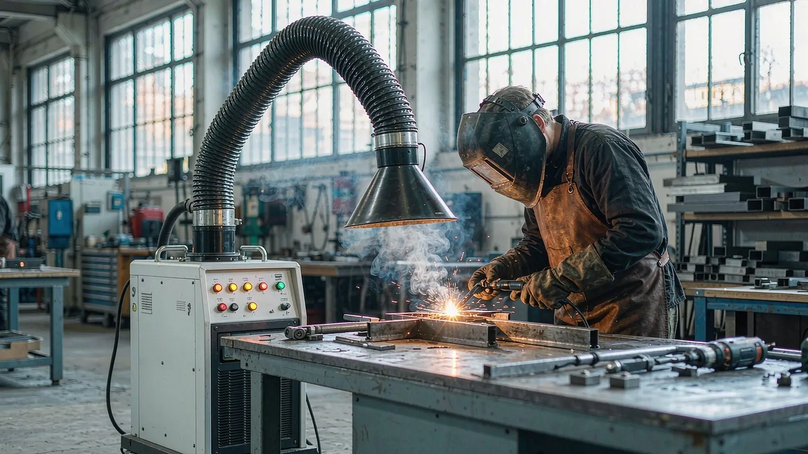
What happens when a central system drifts out of balance
40–80%
Capture efficiency measured by tracer gas on a large-area extraction with a push jet assisting it, varying with the distance between the source and the hood. Large-area capture is a range, not a number — and the range moves with layout.[1]
40% → 60%
Average capture on the same installation, before and after the air jet was switched on. Adding a controlled air path can be worth more than adding airflow to the collector.[1]
10.3–16.8 µg/m³
Manganese measured on bystanders who were not welding, only standing in the same space. In a hall where extraction moves fume across the working area, these are the people the design exposes.[2]
0.5–1.0 m/s
The capture velocity HSG258 expects at a welding arc. On a central system this is the figure that has to survive the opening and closing of every other branch — it is a commissioning measurement at the hood, not a design intention on a drawing.[3]
Full sources are listed under References at the end of this page.
Balance the system, then let it follow the load
A central system is designed from the extraction points backwards: hood, branch, damper, main duct, collector, discharge. Each stage is sized from the airflow the hood needs, and the collector is the last decision rather than the first.
Modular capacity, so growth does not mean replacement
The range is built as modules so capacity is added rather than replaced: FDZY-10P at 12,000 m³/h and FDZY-15P at 17,000 m³/h for smaller halls and multi-bay groups, FDZY-20P at 22,000 m³/h and FDZY-30P at 30,000 m³/h for the mid-range, FDZY-40P at 50,500 m³/h for large halls. The H-series units — FDZY-H16-40H (18,000–20,000 m³/h), FDZY-H132-35H (30,000–35,000 m³/h), FDZY-H48-45H (40,000–45,000 m³/h) and FDZY-H80-90H (90,000–100,000 m³/h) — carry variable-frequency drives, which matters when a hall runs half its extraction points on the late shift: the fan follows the load instead of pulling against closed dampers.
Balance, commission and re-check
Every branch gets a balancing damper and the commissioning records the airflow at each hood with the system configured as it will normally run — not with everything wide open. Dust drops into a lever-type bin on castors for emptying, and cartridges are cleaned automatically on a differential-pressure setpoint. The two things that make central systems fail slowly are unbalanced branches and a filter left to load up; both show up as a hood that stops capturing rather than as a fault indication, which is why the recorded figures from commissioning are the most useful page in the manual.
Modular central collectors
Nine modular collectors cover 12,000 to 100,000 m³/h, with fixed-speed units for steady halls and variable-frequency units where the load changes across the shift.
What a central system installation includes
- Ductwork design with a balancing damper at every branch, sized from the airflow each hood needs rather than from the total
- The collector as a modular unit, so capacity is added as cells rather than by replacing the plant when the hall is extended
- Automatic cartridge cleaning on a differential-pressure setpoint, with dust discharged to a lever-type bin on castors
- Commissioning that records airflow at every hood with the system running normally — plus a marked-up drawing so a later re-check compares like with like
Send the extraction point list: what each hood serves, the airflow it needs and how the hall is used across the shift. Whether the collector is fixed speed or VFD usually falls out of how many points run at once.
Halls and processes this suits
Multi-station welding, cutting and grinding halls in structural steelwork, rail and rolling stock, energy and pressure vessel fabrication, heavy engineering, agricultural machinery and general fabrication. Processes include MMA, MIG/MAG and TIG welding across many bays, plasma and oxy-fuel cutting stations, and grinding and finishing positions. Where the work is concentrated in one bay rather than spread across a hall, source capture at each station usually costs less and captures better than a central system — and where the hall is too large for hoods to reach, blow-suction is the alternative described on the blow-suction page.
In the hall
Questions from plant engineers
Send us the extraction point list
Send us the extraction point list — what each hood serves, the airflow it needs, how many run at once and how the hall is used across the shift. We will come back with the duct layout, the balancing figures and the collector size, fixed speed or variable.
References
- Hynynen P, et al. Local ventilation solution for large, warm emission sources. Ann Occup Hyg 2007. — push-pull ventilation on a large casting area: measured capture efficiency of 40–80% depending on source-to-hood distance, and an average improvement from 40% to 60% with the air jet operating. ovid.com
- Assenhöj M, Ervik T, Graff P, Karlsson H, Ljunggren SA. Impact of preventive measures on welding fume exposure among welders, robot operators, and bystanders. Int J Hyg Environ Health, vol. 276. stami.no
- Health and Safety Executive (UK). Controlling airborne contaminants at work: a guide to local exhaust ventilation. HSG258, 3rd ed. — Table 9 capture velocities for welding fume, and the commissioning checks for a moveable extraction arm. hse.gov.uk
- WorkSafe Queensland (AU). Welding — hazards and controls, code of practice 2021. worksafe.qld.gov.au
- IARC Working Group. Welding, molybdenum trioxide, and indium tin oxide. IARC Monographs on the Evaluation of Carcinogenic Risks to Humans, Volume 118, 2018. Summary: Guha N, et al. The Lancet Oncology 2017;18(5):581–582. doi:10.1016/S1470-2045(17)30255-3
- Health and Safety Executive (UK). Change in enforcement expectations for mild steel welding fume. Safety alert STSU1-2019. hse.gov.uk