
Robotic Welding Fume Extraction
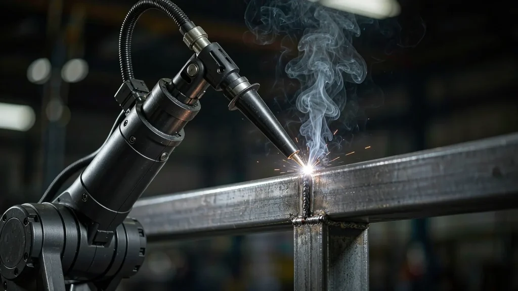
Robotic welding fume extraction is not a scaled-up manual solution. The arc is on for most of the shift instead of 20–25% of it, the torch is guided rather than held, and the operator stands at the cell door — which is exactly where the fume leaves.
96–147 ×10³
particles per cm³ measured at automatic welding machines
4–8×
above the recommended nanoparticle limit in the same measurements
25.2 µg/m³
median manganese found on robot operators, not just the welder
The cell runs all shift, so the fume never stops
A manual welder strikes an arc for a quarter of the shift. A robot holds it for most of it — which is why a cell that looks tidy at nine in the morning still has a haze over it by lunchtime.
Three things change when the torch is held by a machine. The duty cycle goes up, because the robot does not stop for a tack, a phone call or a cup of tea, so the fume generated in an eight-hour shift is several times what the same torch would produce in a manual bay. The fume source is predictable, which is good news for the hood. But the person who used to stand next to it now stands at the cell door watching a screen, and that door is on the exit path of everything the arc produces.
Gantry and turntable cells make it harder again. The work moves and the torch sometimes moves with it, so a hood sized for one position is wrong for the next. The measurements below are the reason robotic cells get their own extraction design rather than a copy of the manual one: the exposure that matters is not only the welder’s, it is the robot operator’s and the bystander’s.
What the instruments recorded
96–147 ×10³ /cm³
Average particle number concentrations measured at automatic welding machines — in the same range as manual arc welding, and dominated by ultrafine particles.[1]
4–8× over
The recommended occupational exposure limits for nanoparticle number concentration were exceeded by roughly four to eight times across every welding operation measured, manual and automatic alike.[1]
25.2 µg/m³
Median manganese on robot operators in one plant, against 146.6 µg/m³ on the manual welders and 16.8 µg/m³ for bystanders. Robot operators are an exposed group in their own right, and so is anyone walking past the cell.[2]
−91%
Reduction in median manganese exposure (146.6 → 13.3 µg/m³) once company-led measures — local exhaust ventilation and working practice — were put in. Extraction is the lever that moves this number.[2]
Full sources are listed under References at the end of this page.
Hood the arc, then size for the duty cycle
The principle is source capture, as it is for any welding fume, but a robotic cell lets you do it properly: the arc stays inside a known envelope, so the hood can be built around that envelope instead of chasing it. The two numbers that decide the design are the capture velocity at the arc and the extraction volume needed to hold the door face.
Hood the envelope, not the torch
For a fixed-position cell the answer is usually an extraction hood or a partial enclosure over the fixture, with the airflow balanced so the fume is drawn away from the operator position rather than across it. For gantry and rail-mounted cells, the hood travels with the carriage on the same rail. On-torch (fume gun) extraction stays an option where the cell is too crowded for a hood — FDYC-2G and FDYC-4G are the high-vacuum units for that duty, and they travel with the torch.
Continuous duty means the filter has to clean itself
A manual bay gets away with a manual-clean cartridge because the arc is off most of the time. A robot does not offer that break, so every unit in this range for cell duty cleans itself: FDYC-30P-S (3,000 m³/h), FDYC-50P (3,000–3,500 m³/h) and FDYC-40Z (3,500–4,500 m³/h) for single cells, FDYC-60Z (5,000–7,000 m³/h) and FDYC-80Z (10,500 m³/h) where several cells are ducted to one collector, with FDYC-30A for cell and booth extraction. Pulse-jet cleaning runs on a differential-pressure setpoint, and a spark arrestor ahead of the cartridge protects the media when the arc is running continuously.
Units for cells, gantries and robot lines
Seven units cover a single cell through to multi-cell ducted installations, on-torch high vacuum included. All of them filter to 0.3 µm and return clean air to the hall.
What a robotic cell installation includes
- An extraction hood or enclosure sized to the cell opening, or a rail-mounted hood that travels with the carriage on gantry cells
- Balancing dampers and ductwork where several cells share one collector, so the airflow at each hood stays where it was commissioned
- Spark arrestor and pre-separation ahead of the cartridge, plus spare cartridge sets for continuous duty
- Commissioning with face velocity measured at the cell door and capture velocity measured at the arc, on both the day shift and the night shift condition
Cell extraction is sized from the cell geometry and the process, not from the number of torches. Send the cell drawings and the cycle time and we will size it with you.
Where robotic extraction gets specified
Robotic MIG/MAG cells in automotive and EV battery tray welding, railway bogie and wagon fabrication, container and pressure-vessel lines, white goods, agricultural machinery, structural steel cells and welding positioner stations. Turntable, gantry, twin-torch and robot-plus-operator (collaborative) cells are all covered. Where the cell is genuinely enclosed and interlocked, the extraction can be sized to the enclosure; where it is open, the operator position has to be designed into the airflow.
On the line
Questions from automation engineers
Send us the cell layout and the duty cycle
Send us the cell layout, the number of torches, the process and the cycle time. We will come back with the hood arrangement, the extraction volume and the ducting, and — where the cell is shared — the balancing figures for each hood.
References
- Occupational exposure to nanoparticles originating from welding — case studies from the Czech Republic. Med Pr 2021;72(3):219–230. PMID 33835113. pubmed.ncbi.nlm.nih.gov — particle number and PM1 mass concentrations for manual arc welding and automatic welding, measured next to the operator.
- Assenhöj M, Ervik T, Graff P, Karlsson H, Ljunggren SA. Impact of preventive measures on welding fume exposure among welders, robot operators, and bystanders: air and biomonitoring. Int J Hyg Environ Health, vol. 276. stami.no
- Health and Safety Executive (UK). Controlling airborne contaminants at work: a guide to local exhaust ventilation. HSG258, 3rd ed. — Table 9 capture velocities for welding fume, and the commissioning checks for a moveable extraction arm. hse.gov.uk
- WorkSafe Queensland (AU). Welding — hazards and controls, code of practice 2021. worksafe.qld.gov.au
- IARC Working Group. Welding, molybdenum trioxide, and indium tin oxide. IARC Monographs on the Evaluation of Carcinogenic Risks to Humans, Volume 118, 2018. Summary: Guha N, et al. The Lancet Oncology 2017;18(5):581–582. doi:10.1016/S1470-2045(17)30255-3
- Health and Safety Executive (UK). Change in enforcement expectations for mild steel welding fume. Safety alert STSU1-2019. hse.gov.uk